Pulse Width Modulation (PWM):
It is modulation technique in which the width of pulse or digital control signals changes with respect to time keeping frequency and amplitude constant. It is used to control the power delivered to any load. It is mainly used to control analog devices.
PWM has low power loss and high efficiency therefore it is used in wide range of operation.

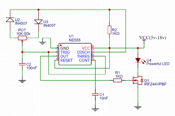
Fig.2 shows brightness control of LED using PWM technique.
The electronic switch is connected between source and LED circuit and the electronic switch is controlled by external control signal.
When switch is closed then entire voltage appear across the LED circuit.
When switch is in open condition then no voltage across the LED circuit.
If we apply control voltage over switch then LED turn ON/OFF rapidly. If the source is of 9v then only 4.5v (average value) appears across the LED circuit.
If switch is on only for 25% then the average value or voltage appears across the LED circuit is 2.25v.
So like this by changing the width of pulse we can control brightness of LED circuit. And same technique is used to control the speed of DC motor. By using PWM technique we can control the brightness linearly.
Generation of PWM Signal:
By using comparator we can generate the PWM signal. By applying triangular wave to the non-inverting terminal and control voltage to the inverting terminal we get PWM signal at the output of comparator. When triangular wave voltage is less than the control voltage then output of comparator gets low, and when the triangular voltage is greater than the control voltage then output of comparator become high. The width of pulse depends on value of control voltage.
As control voltage reduces the width of pulse increases and vice versa.
Switching frequency:
Switching frequency defines as how fast switching takes place. If the switching frequency is higher, then the greater number of times switches changes per second.
Duty cycle:
The Duty cycle defines ON time of pulse. It is ratio of ON time of pulse to total time period. It is expressed in %.
Duty Cycle= Ton/T*100%
If the duty cycle is 25% that means the pulse ON for 25% of the time.
If the duty cycle is 50% that means the pulse ON for 50% of the time.
If the duty cycle is 75% that means the pulse ON for 75% of the time.
Application of PWM:
Dimming the LED lights
Controlling the fan speed of CPU
Controlling the brightness of display in laptops
DC-DC Converters and SMPS etc.
Dimming LED lights:

CPU fan:

Laptop Display:

SMPS:


